 |
||||||||
CIS Component DescriptionsIf highlighted, click on a component name to see a photo.
Accumulator:This device is located in the fuel circuit between the fuel
pump and the fuel filter. There is an internal spring loaded diaphragm
which maintains some residual fuel pressure when the engine is shut off.
A second purpose of the accumulator is to reduce the sharp pressure
increase to the fuel distributor from the fuel pump when it first comes
on. The accumlator delays the fuel pressure spike from microseconds to
about a second. A third pupose is to dampen out some of the noise from
the fuel pump. When the engine is shut off, fuel pressure will normally
bleed off over time, and is not intended to remain over at the most an
hour or so. Some easy to remember approximate numbers for testing
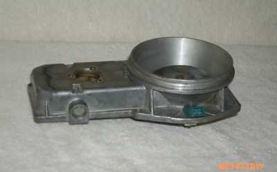
purposes are 15 PSI remaining in 15 minutes after engine shutdown. Air box:The air box is made up of two sections. The top provides a
recess for the air filter, a mounting surface for the sensor plate
assembly, and for the throttle body. The throttle body opens into the
closed bottom section. The lower outputs of the closed section feed the 6
runners for the intake ports of the individual cylinders. At the front
(forward) side of the box is mounted the cold start valve, and the air
intake from the aux air valve, aux air regulator, and deceleration
valve. The 6 airbox output connections and air runners on the 78-79
engines are larger than both the earlier and later cars. In '80 an
internal metal manifold was added to the air box. This manifold routed
the fuel mist from the cold start valve to the inputs of each air runner
to better distribute this mist to each individual cylinder. Prior to
this, the cold start valve sprayed fuel into the open intake manifold
part of the airbox. The later airbox will retrofit to the '74 - '77, but
not the 78-79 without a different rubber connecting sleeve. Air Flow sensor:The airflow sensor plate moves in relation to the air drawn
into the engine, and is connected via a lever arm to a piston in the
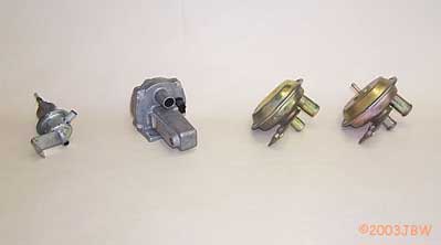
fuel distributor. This piston regulates the fuel flow to the injectors. Air Restrictor:The air restrictor is a small opening placed in the breather line from the rubber boot which connects the air flow sensor to the throttle body. This breather line connects to the oil tank. The purpose of the restrictor is to reduce the influx of unmetered air to the engine when the oil tank cap is removed while the engine is running.Auxiliary Air Regulator :Provides extra starting air (bypassing air around the throttle
body) with a cold engine. The valve slowly closes with heat, provided
by an internal resistor, and to a lesser degree, from heat from the
engine itself. For part number 0 280 140 200 (from a 1976), the cold
resistance of the heater is about 17 ohms. This device was added in '76. Auxiliary Air Valve:Provides bypass air around the throttle when the engine is
first started. When the intake manifold vacuum reaches 5 - 6 inches, the
valve closes. The closing is independent of engine heat. Part number 0
280 160 400 pulls in at ~8" vacuum. This regulator supplies air to the
intake manifold during warm and hot starts when the auxiliary air
regulator is closed. This was added in '76. Cold start valve:Similar to a fuel injector, this device dispenses supplemental
fuel into the air box during cold engine start. It is controlled by
starter voltage and thermotime switch. Control pressure regulator (also called Warm Up Regulator):Drops control pressure when engine is cold, resulting in a
richer mixture during warm up. . The term warm-up regulator is a bit of a
misnomer in that this component actually regulates control pressure the
entire time the engine is running. It changes the pressure during the
warm-up period. Power is applied to bimetal strip in the regulator when
fuel pump is on. As the internal resistor heats up the strip, the
control pressure supplied to the fuel distributor increases, leaning the
fuel mixture. On cars with vacuum control, the WUR enriches mixture
under load determined by lower intake manifold vacuum. It is unclear
when the the Vacuum controlled units were phased in to the CIS. The
Porsche factory workshop manual shows a page for 1974/1975 models with
WUR specifications that include both vacuum controlled versions and
non-vacuum versions. US and ROW model differences may account for this.
Some versions also modify pressure with altitude. Lambda sensor systems
don't use the vacuum chamber because of this adjustment being
automatically accomplished by the lambda system electronics box. '81 saw
a change in the internal resistor configuration for the WUR. A second
resistor was added to heat the bimetallic spring, controlled by a
bimetallic switch. This allows the mixture to lean out more quickly
after start-up,about 2 minutes compared to the former 3 minutes. Deceleration valve:(Also called Auxiliary Air device, or vacuum control.) When
decelerating from high RPM with a closed throttle, this valve prevents
high vacuum in the intake manifold by providing a path for air bypassing
the closed throttle. This provides sufficient air in the air
distribution box for a combustible mixture. It is one of three devices
that bypasses air around the throttle plate. It opens with about 15 to
18 inches of intake manifold vacuum. Deceleration valve 0 280 160 111
pulls in at ~14" Vacuum. This component was supplied in two
configurations on the CIS cars. The first type was on the early cars
through the 79 models. It was mounted on the throttle body on the
"firewall" side, pretty much out of sight. The second appeared on the
'80 through '83 and can be seen on the right hand side of the engine,
behind the fuel distributor. Frequency Valve:This component is used only on the engines with Lambda control. The duty cycle of pulses sent to the device by the Lambda control box varies the pressure in the lower chambers of the fuel distributor, which controls the fuel mixture. Fuel filter:This element is pretty much a no-brainer. It helps keep contamination out of fuel distributor and injectors. Fuel Pump relay:Operation of the '76 and later relay: Fuel pump & check valve:The fuel pump provides fuel at the proper pressure and flow
rate to the accumulator and fuel filter. At the output of the pump is a
check valve, which prevents fuel flow back to the fuel tank when the
engie is shut off. This helps keep fuel pressure in system for
restarting. Fuel Distributor:The fuel distributor has the functions of regulating the fuel pressure, adjusting the fuel flow to the injectors based on the position of the air flow sensor and the control pressure from the WUR. Failure mode: On relatively rare occasions, an internal problem may occur which can result in faulty metering of fuel to one or more cylinders. The fuel distributor is typically not repairable by the DIY'er as the reapir parts are not made available by Bosch. An item in the June issue of the Porsche Panorama magazine (1977) suggests that the units can be rebuilt with a lot of care, but ackowledges that Bosch will not sell internal parts to the public. Injector:The injector opens at ~3.0 bar pressure. The volume of fuel
injected is determined by fuel distributor, and the proper pattern is a
conical spray. Injector lines:The lines were hard plastic through the '79 model year. In '80 the lines were changed to pre-formed steel lines. Intake Runners:The runners provide a path for the air/fuel mixture from the intake manifold to the intake port of each cylinder head. The late 1973 runners were made of formed bent tubing; from 1974 models on, they were of cast aluminum. Oil Breather Restrictor:On year models where the oil tank is vented into the air boot connecting the airflow sensor and the throttle body, this restrictor prevents the engine from stalling when the oil tank cap is removed. Removing the cap without the restrictor would allow enough "false air" to enter the system to stall the engine while checking the oil level. In 1980, the US CIS system was modified to include an O2
sensor system, also called the Lambda system. It consists of the sensor,
the control box, the frequency valve which adjusts the mixture at the
fuel distributor, and several input devices to the control box. The
input devices include an engine temperature sensor, a throttle switch,
and the O2 sensor itself, mounted in the exhaust flow. The basic
function of the Lambda system is to adjust the fuel mixture to
stoichiometric or 14.7:1 air to fuel ratio. This particular air/fuel
ratio enhances the operation of the Catalytic convertor, with which the
Lambda system was designed to operate. The Cat operates more efficiently
in reducing emissions when the fuel mixture is at stoichiometric. On Disabling O2 sensors:Disconnecting the O2 sensor electronics box (and not just the
O2 Sensor) on CIS engines designed to use them will reduce the cold
start enrichment, and the full throttle enrichment. The engine may also
probably lose some gas mileage. Safety switch on air flow sensor:This switch prevents fuel pump from running when ignition key is on and the engine is not running. Thermotime switch:This switch allows operation of the cold start valve at engine
temperatures below 45 Degrees C (113 degrees F) and then only for a few
seconds during starting. Power is applied to the switchs internal
resistor from the starter. The internal resistor heats a bimetallic
strip which interrupts the current flow on the ground side of the cold
start connection. After engine warmup, engine heat is responsible for
holding open the bimetallic strip, so that the cold start valve will not
energize when the starter is operated on a warm engine. Also, after
several unsuccessful starting tries on a cold engine, the internal
resistor will heat the thermotime switch and cold start valve operation
will be inhibited until the switch cools. Thermal valve:Holds off vacuum from the warm-up regulator when engine is
started cold ('77 - '79 engines). Power is applied to the thermal valve
when engine is started, and approximately 30 seconds later, the valve
opens. When the valve is open, vacuum to the WUR is then determined by
the intake manifold. --The vacuum holdoff results in a mixture richening
at warmup. The inner hose connects to the intake vacuum source and the
outer hose to the WUR. Throttle body:The throttle valve controls the air allowed into manifold,
based on accelerator position. The idle air screw adjusts the amount of
air flow around (bypassing) the throttle plate. Throttle operated control pressure regulator:Early CIS only ('73 - '75) Operated by a cam driven off the
throttle shaft. Enriches the mixture at full throttle and at idle by
decreasing the control pressure. Throttle switch 1:Closes one set of contacts at idle to just off idle, closes another at Wide Open Throttle. Throttle switch 2:Closes at idle. Vacuum switch (see Thermal Valve)Warm Up Regulator (see Control Pressure Regulator):WUR Relay:For the '73 CIS cars, the WUR got power directly from a fuse in the engine bay powered from the ignition switch. On the '74 and '75 the wiring diagrams show that the power for this relay is derived from the three diodes in the alternator that go to the charge indicator light. Starting in '76, the same relay that powers the fuel pump powers the warmup regulator. So only whenever the engine is running on the earlier cars, or when the fuel pump is actually running on the later cars, should you have voltage on the WUR (except for the '73 as above). |
|||